Custom Long Range Live Video Solution
The live video solution for Duke AERO's 2026 rocket: Devils Advocate. Running on 3.4GHz using RaptorQ and Reed-Solomon
- Published
- Length
- 19 min read
- Views
- …

Contents · 10 sections
Every year, the Duke AERO club competes at the International Rocket Engineering Competition, or IREC for short. Alongside the main mission of building the rocket and hitting a target apogee, IREC has many side-quests/challenges you can take on, with one such being the: Live Rocket Video & Telemetry Challenge
The premise is simple, record video from onboard the rocket, beam it down to the ground, and combine it with your rocket’s telemetry to create a video stream for viewers to enjoy.
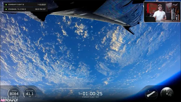 SpaceX’s Starship Flight 13’s onboard live video system
Background
There exist two types of solutions: Digital and Analog. An analog camera has a single output, a wire with fluctuating voltage, called Composite video. You might be familiar with this in the form of RCA (the Red, White, and Yellow cables). And, in the air, it’s modulated in a standard called NTSC for U.S., or PAL in Europe. This system is used a lot by FPV drone pilots because it’s cheap, low latency, small, and fairly reliable.
Digital cameras output digital signals (1s and 0s) and are often much more complicated. USB webcams are an example of a digital camera; they communicate with your computer over USB, a system that uses 1s and 0s. To transmit this in the air, many, many options exist. It can be transmitted over WiFi like when watching a Twitch live stream. Off the shelf solutions exist, such as the DJI O4, but generally are a lot more expensive than analog solutions.
The main advantage digital systems have over analog is the video quality. Modern modulation and compression techniques allow you to fit more data into the air, resulting in a sharper and higher framerate image. NTSC/analog systems typically run at 480p with 29.97 fps, while digital systems can easily push HD 720p or FHD 1080p, with the O4 Air capable of 1080p at 120fps. Digital transmission also carries error correcting codes, allowing for recovery of the original image, while analog video is easily susceptible to noise that fades the transmission.
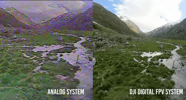 Analog vs Digital transmission courtesy of Tough Stump
Initial Testing
For AERO, we started simple. Many solutions, both digital and analog already exist, targeted at FPV drone pilots.
On the analog side, we used the Matek VTX-1G3 630mW paired with the Caddx Ant analog camera. We paired this with a set of antennas from Video Aerial Systems. On the receiving side, we used a generic VRX receiver from eBay into a USB capture card for recording.
For digital, we took two Raspberry Pis, an ALFA AWUS036ACH on the RX side, an ASUS USB-AC56 on the TX side, and a generic USB webcam. Then we used the QOpenHD app on a smartphone to record the results. For the antennas, we used the generic omnidirectional antennas that came with the two devices, as we did not have any 5 GHz or 2.4 GHz antennas laying around.
Putting it together on this great stick of video, we created this dinglebob:
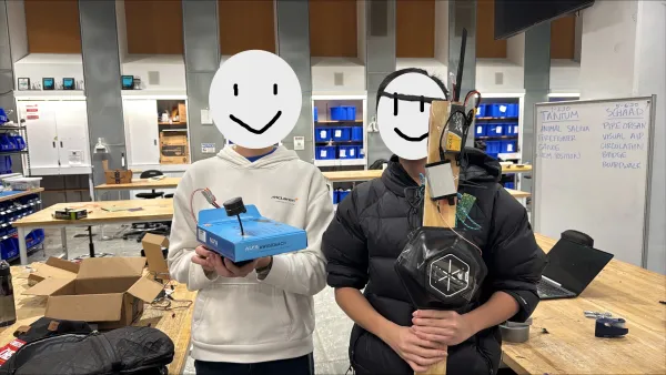 Introducing the box of transmission, and stick of truth.
To put this to the test, we went outside and conducted a mini range test. Duke’s campus is very hilly, so it’s hard to find an area with long line-of-sight within easy reach of the makerspace, so for an initial PoC, we conducted the test in a parking lot.
Despite having a worse antenna array, the digital solution maintained a very clean link. The Analog link had a lot of noise and very frequent dropouts. That said, the analog camera did provide significantly better low-light performance, but for a mid-day rocket launch under the Texas sun (IREC is in Texas), this was not an issue.
It seems we have a winner then! But you may have noticed how the title of this blog says “Custom”. Using an off the shelf solution like OpenHD is not really Custom…
The Twist
Half way through the school year, IREC modified the rules. Originally, 2.4 GHz and 5 GHz were allowed for video transmission, but an updated frequency guide prohibited the use of 2.4 GHz and 5 GHz, presumably because IREC utilizes drones and local WiFi networks for operation, and they did not want the possibility of interference. The new frequency guide was much shorter:
| Band | Type | Lower (MHz) | Upper (MHz) | Power (mW) | Bandwidth (kHz) |
|---|---|---|---|---|---|
| 3.4 GHz (9cm) | Video (only) | 3300 | 3500 | 5,000 | 40,000 |
| 1.2 GHz (23cm) | Video (only) | 1240 | 1300 | 5,000 | 40,000 |
OpenHD makes use of specific WiFi chipsets that have the capability to inject custom packets, lobotomizing the 802.11 protocol to remove anything that may hinder range, making it hyperfocused on video transmission. This allows the project to piggyback off of the chipset’s built-in modem, so OpenHD doesn’t have to worry about the lower PHY layer. Unfortunately, WiFi operates only on 2.4 and 5 GHz (with the exception of HaLow, but that is a completely different situation), so it would be impossible to use OpenHD with the new frequency plan.
Furthermore, finding consumer hardware that can transmit on 3.4 GHz is nearly impossible. The 9cm band requires a HAM radio license (which luckily someone on our team has) compared to 2.4 and 5 which don’t require a license. Equipment in this range is typically for cellular networks and priced for companies like AT&T/Verizon, who have a bit more money than a university team.
And while we could go back to Analog video, where’s the fun in that? It also did not hold up that well in our short range test, so we were quite worried about its ability to transmit the >30,000ft we need it to.
And so the journey for a custom solution began.
Video Encoding for Dummies
At HD 720p, that is pixels. Each pixel needs a red, green, and blue channel, which we can represent as 8 bits each, so bits per frame. At 30 frames per second, that becomes an enormous amount of information, about 660 Mb/s.
When you share a picture online, it’s often in the form of a PNG, JPEG, or WebP. And if you look at the filesizes, they’re almost always a few hundred kilobytes to a few megabytes in size. Now take, for example, the JPEG algorithm, and apply it to every single frame in a video, and you’ve created MJPEG (Motion JPEG).
This is the simplest type of video compression, every frame lives independently of another (known as Intraframe compression). If a standard 720p JPEG is around 250kB, and we want 30fps, that is 7.5 MB/s or 60 Mbps. That’s a lot better than sending raw images, but a reliable 60Mbps link is still tough to establish over a long distance.
So back to the drawing board. If you imagine a video of a small object moving left to right, between frames, the only thing that’s actually changing is the object. So, what if we encode only this difference? That’s Interframe compression.
This introduces a new problem, if a receiver doesn’t have the original image, all the delta encodings are useless. I can’t say “move these pixels to the right” if the receiver doesn’t have the original pixels. To solve this, every few frames, a new full frame (like a full JPEG) is sent. Then the next frames are all deltas off of this. If you are a receiver tuning in for the first time, you have to wait until you get one of these full frames, then you can start displaying video.
Engineers have created specific terms for this:
- I-frame (Intra-frame) contains the data for a full independent frame, and is often known as a keyframe.
- P-frame (Predicted-frame) contains the delta data between this frame and the previous I- or P-frame.
- B-frame (Bi-directional) references both past and future frames. They compress better, but force the decoder to wait on frames that haven’t arrived yet, so we leave them off to keep latency down.
- GOP (Group of Pictures) is the group of one I-frame and its following P-frames.
Balancing the size of the GOP is important. A larger GOP means higher compression, as P-frames are much smaller than I-frames, and a larger GOP means each I-frame has more associated P-frames, but having more P-frames means receivers need to wait longer to receive a I-frame and start decoding. Since I-frames are larger than P-frames, over a lossy wireless connection, it is more likely for you to lose an I-frame, which would then invalidate all the following P-frames. This creates an effect you may have seen called “data moshing” where I-frames are purposely removed to create a really trippy effect:
An example of datamoshing posted on Instagram by @aescripts
There exist many modern video codecs (formats) we can use. H.264 is one such example, and is very commonly used on the Internet. A 720p30 stream is comfortable at around 5 Mbps with H.264, but our radio link ends up giving us well under half of that once error correction takes its cut. So we settled on H.265, the successor to H.264. It’s roughly twice as efficient at the same quality, which buys back the bitrate we don’t have, at the cost of more processing power to encode and decode.
Creating the RF Link
The next hurdle is the transmission itself. How do we transmit signals in the air? The answer is RF black magic. This is a really deep rabbithole, one I’m not yet qualified to teach in a short blog post. But I’ll give a really basic overview.
Modulation is the act of turning data into I/Q signals that can be transmitted in the air, common forms are:
- AM or Amplitude Modulation, used in long distance radio.
- FM or Frequency Modulation, also used in radio. You likely have an FM receiver in your car to listen to music from local stations.
- *PSK family, used in early WiFi and in satellite links, with modest but reliable speeds.
- *-QAM family, used in newer WiFi standards for higher speeds, at the tradeoff of range.
We settled on QPSK for its balance between speed, computational requirements, and range. After spending many, many hours trying to create a working modem (modulator and demodulator) in GNURadio, we kept falling short of the finish line. The first prototype could send data over a Channel Model (basically a fake radio link), but when we introduced actual transmitter and receiver hardware, things would fall out of phase very quickly, or the data we receive would be offset by a few bits.
To break the problem down, I took a page out of networking and followed the OSI model:
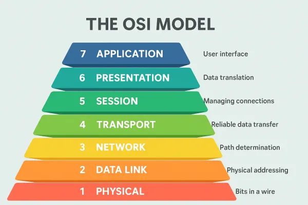 OSI Model, image from Network Supply
I created a custom Rust app that used gstreamer, a framework for creating video processing pipelines. The USB camera produces a MJPEG output, which is fed into an MJPEG decoder and DMA’d over to the H.265 encoder. This outputs NALUs (Network Abstraction Layer Units), which is our application layer data.
Connections are sessionless, essentially a broadcast network. A header is added for handling sequence IDs for out-of-order delivery, payload size, checksum, and forward error correcting is added. This is fed over ZMQ to GNURadio to handle modulation, with a preamble added, sync bits added, and add packet interleaving. This makes up the link, network, and transport layers. Finally, GNURadio streams this to a Software Defined Radio (hardware that can transmit arbitrary signals) for the actual physical layer.
You can see how this quickly got out of hand. Debugging issues was a nightmare, and every issue introduced a new part into our software stack, quickly eating away at our margins.
So, I took a step back, and found that solutions already exist. DVB-S/DVB-S2 is one such protocol that exists. It can run over QPSK, and incorporates everything I was manually implementing, standardized and battle-tested decades ago.
DVB-S expects an MPEG-TS input. This is simple to add, gstreamer and ffmpeg both support mpegts outputs.
Side note: MPEG-TS is the container format, it’s what provides a nice header to the data, where the underlying data is the output from an H.265 encoder. Without it, decoders don’t know where packets start and end, and what parameters to use for decoding. It also allows for some extra goodies to be transmitted, like a stream title and description.
Error Correcting
When data travels in the air, it is subject to many different interference patterns, like multipath, where signals take different routes in the air, bouncing off different objects, and causing them to arrive at different times and can cancel other signals out. There’s also the normal background noise, or null zones in the radiation pattern of an antenna. Needless to say, RF signals have it rough.
So we must correct for the possibility of information arriving slightly corrupted or missing. Compression works against us here, as the goal of compression is to reduce the amount of redundant information. You saw previously what a lost I-frame can do to video.
Both DVB-S and DVB-S2 employ error correcting algorithms. DVB-S2’s Low Density Parity Check (LDPC) codes are the stronger of the two, but they were far too heavy for our CPU, and offloading them to the FPGA on our SDR didn’t pan out either (more on that later). So we resorted back to DVB-S framing and ran Reed-Solomon on CPU, which had plenty of headroom.
DVB-S was optimized for Additive White Gaussian Noise (AWGN), where the sender and receiver are mostly stationary (you’re not hauling your analog TV past mach 1). Our rocket is a much more dynamic story, so to compensate, we added one more layer of FEC to the mix: RaptorQ.
RaptorQ is a fountain erasure code. Given N source packets it can generate an unlimited number of unique repair packets, and a receiver that collects any N+2 of them rebuilds the original data with near-certainty, it doesn’t matter which ones arrive.
That pairs well with variable bitrate video. Still frames compress smaller, so the encoder emits less data. Our rate on the air is fixed, so rather than idle, the slack gets spent on extra repair packets. We cap the encoder below the channel rate so there’s always room for at least K extra repair packets, K > 2, even during the busiest frames.
Hardware
To run this stack, we chose a Radxa Zero 3E.
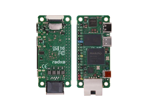 Radxa Zero 3E Product Photo.
It features a quad-core ARM CPU with onboard hardware accelerated H.265 encoding. H.265 is slow to encode on a CPU, so having hardware acceleration will greatly lower the load for the CPU, leaving more room to create the DVB-S signal.
The Radxa Zero 3E also has an ethernet port, hence the E suffix, which will be used to communicate with the SDR, with the remaining USB ports being used for power and camera connection.
For the SDR, we chose the OpenSourceSDRLab Zynq 7010 + AD9361 board, chosen because it is a great value board, and one of the only boards in this price range that include some sort of high-speed connection option. Most boards are limited to USB 480Mbps, while this can do gigabit over Ethernet.
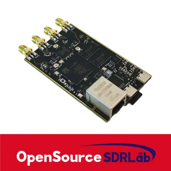 OpenSourceSDRLab Zynq 7010 + AD9363
Software stack
A lot of effort was initially put into trying to accelerate the dvb encoding by using the FPGA. Specifically, if we could offload the low density parity checking (LDPC) code generation to the FPGA matrix, we could use DVB-S2, allowing greater bandwidth. But after spending days, I kept running into firmware on GitHub that just shipped precompiled binaries or were missing the Xilinx project, shipping only prebuilt FPGA bitstream.
Eventually I found tezuka-fw, which had a recent commit to add dvb encoding. Spent a while building and flashing our SDR, just to find that our SDR with the Zynq 7010 was unsupported as it didn’t have enough logic cells 🫠
Anyways, you can read my struggles in detail here. So, I dropped back to use DVB-S (not S2) which uses Reed-Solomon FEC codes, much lighter than LDPC. Using GNURadio I created a flowgraph to pull data from a local IPC socket, run the encoding, and push to the SDR.
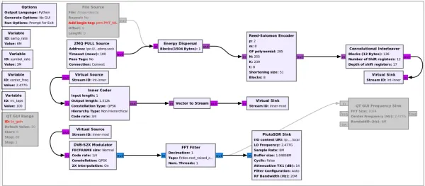 GNURadio flowgraph
On the pushing side of the socket, a script started ffmpeg that pulled the feed from our camera, overlayed it with our callsign, and encoded as H.265. A small buffer is added to handle small jitter, and this is piped to the raptorq encoding program. This program then pushes to the ZMQ IPC socket.
#!/usr/bin/env bash
# pipeline that utilizes hardware accel as much as possible##   v4l2 (MJPEG) -> mjpeg_rkmpp (HW decode, DRM frames)#                -> overlay_rkrga (HW blend of a pre-baked DUKE AERO layer)#                -> [nv12 via RGA] -> hevc_rkmpp (HW encode)#                -> mpegts (VBR) -> mbuffer -> raptorq -> ZMQ## Goal: keep frames in DRM memory end-to-end so the CPU is freed for the# software DVB-S modulator.#set -euo pipefail
### INPUT configurationDEVICE="/dev/video0"WIDTH=1280HEIGHT=720FPS=30
RC_MODE="${RC_MODE:-VBR}"               # VBR | AVBR | CBRTARGET_BPS="${TARGET_BPS:-1500000}"     # -b:v     encoder target; dips lower on easy scenes (VBR/AVBR)MAXRATE_BPS="${MAXRATE_BPS:-2300000}"   # -maxrate hard ceiling (bits/s); keep <= channel payload capacityMINRATE_BPS="${MINRATE_BPS:-0}"         # -minrate floor (bits/s); keep 0/low so quiet scenes free bits for repairBUFSIZE_BITS="${BUFSIZE_BITS:-2300000}" # -bufsize VBV window (bits); smaller = tighter per-burst/I-frame capGOP="${GOP:-60}"                        # keyframes every 2 s (GOP / FPS)BFRAMES="${BFRAMES:-0}"                 # -bf      B-frames; 0 for low latencyREPEAT_HEADERS="${REPEAT_HEADERS:-1}"   # 1: re-send VPS/SPS/PPS before every keyframe so the RX can join mid-streamMUX_BITRATE="${MUX_BITRATE:-2900000}"   # only used by the CBR-TS fallback (see bottom comment)
### OUTPUT configuration# Symbol rate * 2 (QPSK) * 3/4 (FEC rate) * 188/204 (RS overhead)RAPTORQ_MUXRATE=3594117ZMQ_SOCK="${ZMQ_SOCK-ipc:///run/user/1000/raptorq.sock}"
FFMPEG="${FFMPEG:-/usr/lib/jellyfin-ffmpeg/ffmpeg}"FONT="${FONT:-/usr/share/fonts/truetype/dejavu/DejaVuSans-Bold.ttf}"RAPTORQ_ENC="${RAPTORQ_ENC:-./raptorq/target/release/raptorq-enc}"OVERLAY_PNG="${OVERLAY_PNG:-/run/live-video/duke-aero-overlay.png}"
MBUF_SIZE="${MBUF_SIZE:-1M}"
mkdir -p "$(dirname "$OVERLAY_PNG")"if [[ ! -f "$OVERLAY_PNG" ]]; then    echo "[*] Baking overlay -> $OVERLAY_PNG"    "$FFMPEG" -hide_banner -loglevel error \        -f lavfi -i "color=c=black:s=260x48:d=1" \        -frames:v 1 \        -vf "drawtext=fontfile=${FONT}:text='DUKE AERO':x=12:y=10:fontsize=24:fontcolor=white,format=rgba" \        -y "$OVERLAY_PNG"fi
FILTERGRAPH="[1:v]format=bgra,hwupload[ovl];[0:v][ovl]overlay_rkrga=x=10:y=10:eof_action=repeat[ov];[ov]scale_rkrga=format=nv12[venc]"
# Assemble HEVC rate-control args from the vars above. -minrate only when set,# so VBR/AVBR are free to floor on static scenes.RC_ARGS=( -rc_mode "$RC_MODE" -b:v "$TARGET_BPS" -maxrate "$MAXRATE_BPS" -bufsize "$BUFSIZE_BITS" )(( MINRATE_BPS > 0 )) && RC_ARGS+=( -minrate "$MINRATE_BPS" )
# Re-emit parameter sets before each keyframe. The rkmpp encoder writes# VPS/SPS/PPS once at startup; an RX that tunes in afterwards never sees them and# its decoder stalls (ffplay sinks bytes forever). dump_extra is encoder-agnostic# and skips packets that already start with the headers, so it's safe to leave on.HDR_BSF=()(( REPEAT_HEADERS )) && HDR_BSF=( -bsf:v dump_extra=freq=keyframe )
FFMPEG_CMD=(  "$FFMPEG" -hide_banner -loglevel warning -stats  -init_hw_device rkmpp=rk -filter_hw_device rk  -fflags nobuffer -flags low_delay  -hwaccel rkmpp -hwaccel_output_format drm_prime -hwaccel_device rk -c:v mjpeg_rkmpp  -f v4l2 -input_format mjpeg -video_size "${WIDTH}x${HEIGHT}" -framerate "$FPS" -i "$DEVICE"  -i "$OVERLAY_PNG"  -filter_complex "$FILTERGRAPH"  -map "[venc]"  -c:v hevc_rkmpp "${RC_ARGS[@]}" -g "$GOP" -bf "$BFRAMES" "${HDR_BSF[@]}"  -f mpegts -flush_packets 1  pipe:1)
echo "[*] HW TX pipeline starting:"printf '    %q ' "${FFMPEG_CMD[@]}"; echo
"${FFMPEG_CMD[@]}" \  | mbuffer -m "$MBUF_SIZE" 2> >(stdbuf -o0 tr '\r' '\n' >&2) \  | "$RAPTORQ_ENC" --rate "$RAPTORQ_MUXRATE" --output-sock "$ZMQ_SOCK" zmq
The Raptorq program has some smarts too, it will do packet interleaving. So if there is a sudden momentary spike to 50% packet loss, for example, then we aren’t losing 50% of the packets for one frame. Instead, it’s spread out, so maybe 10% loss for 5 frames. This can be recovered from, while 50% loss for one frame results in a lost frame.
The raptorq program also ensures that the GNURadio flowgraph never underruns. If the ffmpeg pipeline slows down and produces less data, raptorq program ensures a consistent output bitrate by either padding with noop blocks or extra repair blocks for previous frames.
You can view the repository on GitHub.
Reciever
On the ground side, we used the same SDR with SDRAngel which demodulates the QPSK DVB signal and pushes it the opposite raptorq program for decoding, then piped to ffmpeg for playback.
To help with link quality, we wanted to use Viterbi which SDRAngel supports. But even on my laptop’s i9 13900H processor, we could not demodulate at full speed. After digging into the SDRAngel source code, I found it uses leandvb for demodulation, and the process is entirely single core. I rewrote the algorithm to use SIMD instructions which offered up to a 70x improvement in throughput!
You can find this patch also on GitHub.
Results
Unfortunately all this took too long for our development cycle and ended up not making it onto the rocket during the IREC launch, but we plan on improving and using this system in the upcoming years, so stay tuned for that.
But that doesn’t mean I don’t have results! I did a quick range test at the largest park I could find. I set it up with a 500mW power amplifier and an omnidirectional antenna on the TX side. The RX side used a generic wideband log periodic antenna. I was able to make it across multiple fields at the park, pretty much going as far as I could before trees started breaking line of sight.
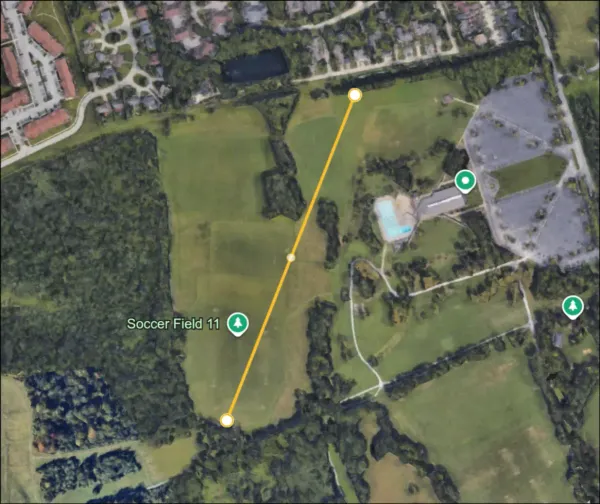 Around 500 meters of distance
At this range, I was able to get stable video if I pointed the RX antenna at the transmitter, which proved to be difficult as I was juggling my laptop, SDR, phone, and antenna in my hands. With a higher power PA and a higher gain Yagi antenna, I know this solution will have great potential.
Where the system landed:
| Parameter | Value |
|---|---|
| Video | 720p30 H.265, 1.5 Mb/s target, 2.3 Mb/s ceiling |
| Modulation | QPSK, DVB-S framing, Reed-Solomon FEC |
| On-air payload | 3.59 Mb/s, constant |
| Extra FEC | RaptorQ, repair fills whatever video leaves |
| Band / power | 3.4 GHz, 500 mW PA |
| Demonstrated range | ~500 m, omni TX, log periodic RX |
So, in conclusion, I’m quite happy with how this ended. The system wasn’t really designed with latency in mind, so there’s much to do in that regard, but I already have plans for how I want to improve the setup for the 2026-2027 IREC competition. Check back in a year, and maybe I’ll have an updated blog post.
This post ended up being quite technical, and I hope I did a good job explaining everything. If you’re curious or have additional questions, feel free to contact me or use the comments field below.